Arrow II ProjectTechnical Details |
|
Delta Wing Profile and a Brief Explanation of the Arrow II Wing Form:
Why is the Arrow II Airfoil ‘Upside Down’?
Why is the Arrow II Airfoil ‘Upside Down’?
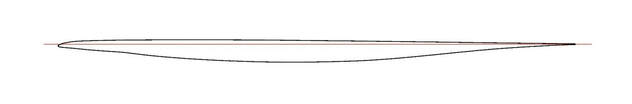
This is an often-asked question. When you look at the airfoil used for the Arrow II wing it looks like, according to Bernoulli, that it should create a downwards force. If the wing operated level to the flight path of the aircraft this would be the case, but that is not actually how a wing works.
The airfoil used on the Arrow II belongs to a class known as supercritical airfoils. They are designed for superior performance at speeds near the speed of sound (as with the Arrow II) and past the speed of sound (in the case of the CF 105). Follow this link for a good in depth explanation of this airfoil type. https://aviation.stackexchange.com/questions/19662/what-are-the-advantages-of-the-b747-8-airfoil-over-b737s-airfoil.
In reality, the primary way that a wing flies is by pushing air downwards. This creates a resulting force of lift that acts against the surface of the wing and allows the airplane to stay in the air. How much air is ‘pushed’ down is a function of the speed of the aircraft and the angle of the wing to the airflow. You can experience this when you put your hand out the window of a fast-moving car. The more you tilt your hand, the greater the lift. So it is with the wing on the Arrow II. Slow flying airfoils can improve lift by adding curvature to the upper surface. For high speed airfoils the curvature on the upper surface can cause premature airflow separation and a lot of drag. The Arrow II has a root chord of 6.8m (22.2ft) – long by any standard. Controlling the airflow separation over the top of this wing is a challenge and is the main reason why the airfoil is shaped the way it is.
An airfoil’s primary job is to allow air to move smoothly around the structure of the wing. Variations in the shape are often dictated by optimizing drag/lift efficiency for a given wing shape, or structural requirements for weight or landing gear stowage.
Fuel Tanks and Fuel Systems:
Many of the visitors to the Museum have asked the questions about the fuel tanks and where they will be located in the airframe. Here we will give you as complete explanation as possible.
In the original Avro Arrow, there were sixteen fuel tanks in the wings that were pressurized and fuel pumps were used to allow the flow from various tanks during specific flight conditions (breaking the sound barrier, for instance) to correct the centre of gravity/lift.
In the Arrow II, there will be four fuel tanks and these will all be located above the air intake tubes within the fuselage. The tanks are fabricated from epoxy impregnated fibreglass covered foam board – a method tested for nine years using four mini-tanks filled with jet fuel by the museum which proved the viability of such construction. They will be suspended between the wing spars, the forward and largest tank (fuel capacity approximately 1,500 lbs or 834 litres) between the forward spar and the front main spar. The mid tank (fuel capacity approximately 400 lbs or 222 litres) will be located between the two main spars. The two rear tanks (total fuel capacity approximately 300 lbs or 167 litres) will be located between the rear main spar and the ‘box’ spar. These fuel tanks will give the Arrow II a range of approximately 1,500 nautical miles.
Due to the normal flying position in level flight, which is slightly nose high, gravity helps feed the fuel to fuel manifold at the rear. Each tank will have the following openings – inspection hatch; filler points and air release points; fuel gauges; fuel temperature sensors; filtered supplies to the fuel manifold and the fuel pumps for the engines supply.
All the tanks have internal baffles that will reduce the impact of fuel movement during aircraft maneuvers. The two (rear) header tanks will also have one-way valves for the rear half of the tank to prevent fuel moving away from the engine supply side of the tanks.
In general terms, the main and mid fuel tanks supply fuel to the manifold at the rear of the fuselage. The two (rear) header tanks are connected to fuel pumps that supply fuel to each of the engines separately from the rear half of those tanks which have one way trap valves to prevent fuel moving to the forward section of the same tank. Fuel from the front half of these two tanks will flow into the manifold and be circulated back with auxiliary pumps from the manifold to the front half of them, ensuring that they are always full.
Fueling the aircraft (a) will take place through the upper tunnel wall (the tunnel stretches from the aft cockpit down to the tail fin) and will fill the main and mid fuel tanks (lines in green). Once the aircraft has had its initial fill, the auxiliary pumps will prime the rear fuel tanks’ front and aft sections, air being expelled from all tanks through air lines (b) located at the top of the tanks (lines in blue). The air-lines will also act to release any build of pressure in the rear tanks when the engines are throttled back, etc. causing a change to the flow rate of fuel.
All remaining fuel supply lines are represented in with black lines.
The schematic diagram below should assist you in understanding this fuel system.
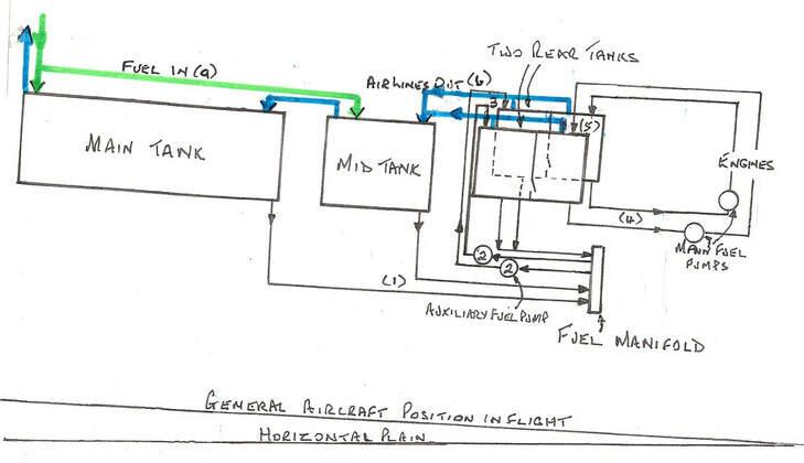
Fuel from the main tank and the mid-tank will only flow (1) into the fuel manifold. The outlet from the manifold leads to auxiliary pumps (2) that will keep the two rear tanks filled (3) on the upside of the baffle containing the one-way valves and through these one-way valves, to the engine supply side of the rear tanks.
The second pumps, the main fuel delivery and circulation pump for the engines, will both pump and heat the fuel from the two (rear) header tanks (4), and will also circulate fuel back to those rear tanks on the delivery side of the baffles (5) with the one-way valves.
Through the use of the main full pump for the engines and the auxiliary pump from the fuel manifold the fuel will continuously circulate through the front and aft sections of the rear tanks, ensuring that these two tanks always remain full.
Strength of materials used on the Arrow II replica
As those of you who have been following our progress on the Arrow II already know, the airframe is primarily constructed from fibreglass and carbon fibre. We thought that you might be interested in the strength of these two materials. Because of the nature of these materials, we always use nitrile or leather gloves when handling either fibreglass or carbon fibre in order to protect our hands and to prevent surface contamination by the natural oils in our skin.
Carbon fibre rod and cloth
The carbon fibre rod comes to us in long coils – approximately 1,000 feet per coil. It is just like spring steel (but 10 times as strong) and the volunteers have to be very careful when un-coiling it for use in our construction using leather gloves for protection. The bar material, composed of long lengths of carbon fibre strands bundled and bonded together under pressure, has a 0.220 x 0.094 inch cross section and in this ‘raw’ condition a single piece of the rod could lift about 6,500 lbs. before breaking. We use a diamond wet saw to cut the material to the lengths that we require. When needing extreme strength, the rods are bundled together using epoxy glues to create these composite pieces for use as, for instance, in the caps on the wing spars. These may have as many as 32 rods in a bundle. These bundles are so strong that they cannot bear directly against each other on the ends so we use thin aircraft-steel plates between the ends of the bundles to act as end bumpers.
Carbon fibre cloth
The woven carbon fibre cloth is made up of a weave of carbon fibre strand bundles. In its raw form is soft to the touch and is difficult to manage when cutting as it will easily unravel. However, when several layers are bonded together with epoxy glues, it becomes a very strong material. The spars, for instance, are made up of 12 layers of carbon fibre cloth laid down with the grain at 45⁰ angles to each other; subsequently, spar caps are bonded to the flat spar stock. This produces a spar that can withstand ±15 g’s of force.
Fibreglass cloth/epoxy combination
Once again, the raw cloth is soft to the touch and is made up of a weave of fibreglass strand bundles. It is used with epoxy glues to cover foam board surfaces to produce a rigid and strong material for various uses. The whole fuselage is constructed of this combination of materials, as are the ribs in the wings. Fibreglass is also used to join various surfaces together. When applied correctly, a double layer of fibreglass cloth/epoxy glue bonding produces a joint that can withstand 500 lbs. of force per inch length of the joint. If this layering is increased, the strength of the joint increases significantly (4 layers produces a joint strength of 1,200 lbs. per inch). Therefore when you consider the joints within the wing, some of which are approaching 20 feet in length, these joints have phenomenal strength.
Wait a minute; You’re gluing the wing on to the fuselage for the Arrow II?
Well, yes but using very particular and extremely strong materials and methodology. Read on.
Although we use the term “bonding the wing to the fuselage”, this is not a simple task. There are no bolts! This connection must be able to withstand some 10 G forces, not from flight alone which will be restricted to a maximum of 5 to 6 G’s but from the effects extremely heavy turbulence or a very heavy landing.
Prior to any bonding work, the fuselage and wings are mated together and supported on various cradles and wooden platforms. Then a transit was used to level both fuselage (side to side and lengthwise) and the wing on the fuselage within fractions of an inch. After more than one week, the levelling was checked again to ensure no movement had taken place. The leading edge of the wing was required to be 1/16” below the top of the fuselage to allow for the future mating of the upper wing skins to the fuselage, giving a smooth transition. The final levels were confirmed to be within 5/1,000” of the exact requirement, less than the width of a pencil line.
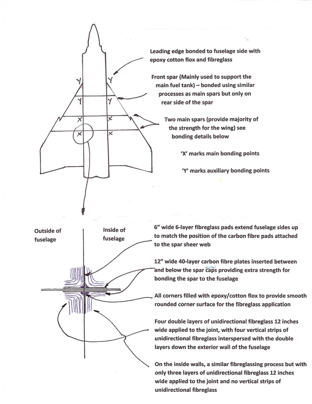
There are eight attachment points between the fuselage and the wing. Remember that the two main spars in the wing are rated at 15 G’s. Four of these joints, where the two main spars connect with the fuselage, are the key strong points. First, 0.4” thick carbon fibre plates (comprised of 40 layers of carbon fibre cloth sealed together with epoxy) are bonded in between the carbon fibre rod caps on the spar webs and these spread 6” each side of the fuselage wall. Then 8” by 6” six layer fibreglass pads are bonded on to the fuselage walls, extending the walls up alongside the carbon fibre plates. In both cases, T88 epoxy – amongst the strongest epoxy product – is used for the bond. (See the diagrams on the next page.) At this point, the next element of the bonding process is preceded with an epoxy/flox filet being shaped in each of the four segments of each joint followed by multiple layers of unidirectional fibreglass epoxied in place between the carbon fibre plates and the fuselage wall and extensions. The twelve (12) layers of fibreglass jointing fabric are utilized as follows on the outside of the fuselage wall; first, a double layer with the grain of the fibreglass laid diagonally across the joint with the two layers grain at 90 degrees to each other – this joins the spar to the fuselage side; next a long single layer of fibreglass is laid with the grain vertically over the previous layer on the fuselage, extending down the side of the fuselage at varying lengths from 8 inches down to 5 inches on the final layer. This is repeated three more times providing twelve full layers of fibreglass. A similar process is used on the inside walls of the fuselage but utilizes only bi-directional fibreglass with three (3) layers of double fibreglass cloth, the bias at 90 degrees to each layer. This provides exceptional strength of approximately 44,000 lbs. shear strength per joint or 176,000 lbs. strength between the four main connection points between the spars and the fuselage. This provides much more than the 10 G connection requirement.
Beyond these four joints on the two main spars, there are four more connection points that add to the wing/fuselage connection strength - the forward spar and the leading edge connection point to the fuselage wall. The forward spar was treated similarly to the main spars but only on the rear side of the spar – a carbon fibre plate on sheer web of the spar and a fibreglass pad alongside it whereas the leading edge connection relies upon epoxy/flox filets followed by multiple fibreglass layers. These last four joints do add some additional strength overall for the attachment of the wing to the fuselage but the main strength comes from the connections on the two main spars. The following page of diagrams will help explain the above narrative.
Well, yes but using very particular and extremely strong materials and methodology. Read on.
Although we use the term “bonding the wing to the fuselage”, this is not a simple task. There are no bolts! This connection must be able to withstand some 10 G forces, not from flight alone which will be restricted to a maximum of 5 to 6 G’s but from the effects extremely heavy turbulence or a very heavy landing.
Prior to any bonding work, the fuselage and wings are mated together and supported on various cradles and wooden platforms. Then a transit was used to level both fuselage (side to side and lengthwise) and the wing on the fuselage within fractions of an inch. After more than one week, the levelling was checked again to ensure no movement had taken place. The leading edge of the wing was required to be 1/16” below the top of the fuselage to allow for the future mating of the upper wing skins to the fuselage, giving a smooth transition. The final levels were confirmed to be within 5/1,000” of the exact requirement, less than the width of a pencil line.
There are eight attachment points between the fuselage and the wing. Remember that the two main spars in the wing are rated at 15 G’s. Four of these joints, where the two main spars connect with the fuselage, are the key strong points. First, 0.4” thick carbon fibre plates (comprised of 40 layers of carbon fibre cloth sealed together with epoxy) are bonded in between the carbon fibre rod caps on the spar webs and these spread 6” each side of the fuselage wall. Then 8” by 6” six layer fibreglass pads are bonded on to the fuselage walls, extending the walls up alongside the carbon fibre plates. In both cases, T88 epoxy – amongst the strongest epoxy product – is used for the bond. (See the diagrams on the next page.) At this point, the next element of the bonding process is preceded with an epoxy/flox filet being shaped in each of the four segments of each joint followed by multiple layers of unidirectional fibreglass epoxied in place between the carbon fibre plates and the fuselage wall and extensions. The twelve (12) layers of fibreglass jointing fabric are utilized as follows on the outside of the fuselage wall; first, a double layer with the grain of the fibreglass laid diagonally across the joint with the two layers grain at 90 degrees to each other – this joins the spar to the fuselage side; next a long single layer of fibreglass is laid with the grain vertically over the previous layer on the fuselage, extending down the side of the fuselage at varying lengths from 8 inches down to 5 inches on the final layer. This is repeated three more times providing twelve full layers of fibreglass. A similar process is used on the inside walls of the fuselage but utilizes only bi-directional fibreglass with three (3) layers of double fibreglass cloth, the bias at 90 degrees to each layer. This provides exceptional strength of approximately 44,000 lbs. shear strength per joint or 176,000 lbs. strength between the four main connection points between the spars and the fuselage. This provides much more than the 10 G connection requirement.
Beyond these four joints on the two main spars, there are four more connection points that add to the wing/fuselage connection strength - the forward spar and the leading edge connection point to the fuselage wall. The forward spar was treated similarly to the main spars but only on the rear side of the spar – a carbon fibre plate on sheer web of the spar and a fibreglass pad alongside it whereas the leading edge connection relies upon epoxy/flox filets followed by multiple fibreglass layers. These last four joints do add some additional strength overall for the attachment of the wing to the fuselage but the main strength comes from the connections on the two main spars. The following page of diagrams will help explain the above narrative.
Avro Museum Arrow II Flight Simulator
Then and Now
The CF-105 simulator used by AVRO CANADA in 1958 consisted of a fixed base wooden fuselage section which contained the pilot and the weapons officer compartment in tandem. Instrumentation was operational for simulation requirements with some non-functioning switches and indicators. The flight instruments were operational and included a noise generator to simulate engine noise. Unlike many military and commercial simulators today, it did not provide any motion to simulate flight. The CF-105 simulator was used to validate the flight characteristics of the aircraft at altitude and weapons control systems. The state-of-the-art computers (in that day and age) were located in a 1600 square foot air-conditioned room. The simulator continued in use until the program was cancelled in February 1959.
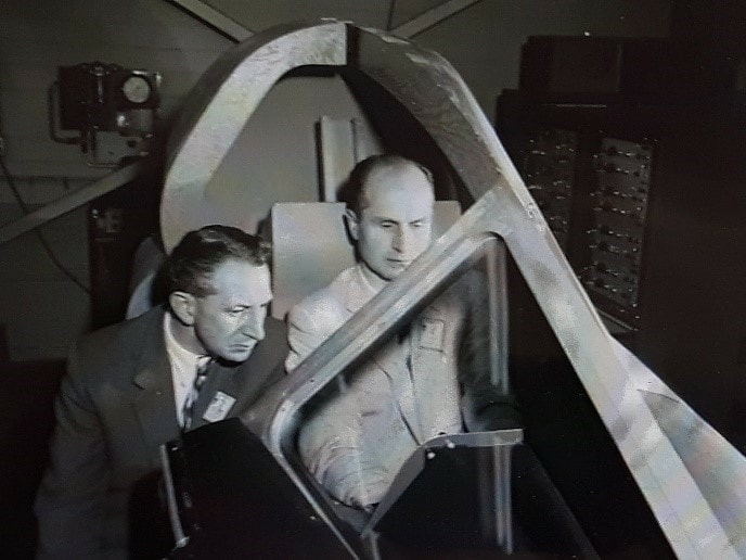
Jan Zurakowski and Wladyslaw “Spud” Potocki in the Avro Arrow Simulator 1959
At the Avro Museum hangar at Springbank Airport, we have built our own simulator. Like its predecessor, it is also a fixed base wooden fuselage section. However, it does not have a seat for the weapons officer.
At the Avro Museum hangar at Springbank Airport, we have built our own simulator. Like its predecessor, it is also a fixed base wooden fuselage section. However, it does not have a seat for the weapons officer.
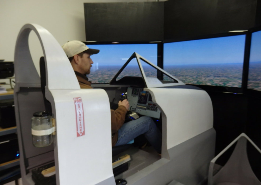
The Arrow II simulator is powered by five computers running X-PLANE, the most comprehensive and powerful flight simulator program for personal computers. Three large screens provide the pilot’s view of the surrounding landscape and airports. There is an auxiliary screen that can show various angle views of the Arrow II during the flight. It provides us with a very sophisticated state-of-the-art engineering tool as well as a flight simulator. The specifications of the Arrow II have been programed into the X-Plane program. This sophisticated professional software tool uses an aerodynamic model known as BLADE ELEMENT THEORY.
It has been used by private and commercial enterprises alike for aircraft design and testing as well as training of pilots. We are able to verify the performance of different engine types that may be selected for final installation in the Arrow II. Phases of flight such as take-off, cruise flight and landing along with critical system failures allows us to determine how the aircraft will perform in the real world. Based on the design parameters of the Arrow II and the functionality of our X-Plane Simulator program, we feel confident knowing the flight characteristics of the Arrow II prior to actual flight testing.
To date, the Avro Museum has invested close to $50,000 in the development of this simulator which is quite expensive to operate and is definitely NOT A TOY. Instrumentation for our flight simulator (under development) is functional for flight training and testing and provides a true to life experience of flying the Arrow II.
The simulator may be used by members whose membership is current and volunteers in the museum at no charge. Even so, their use will be supervised as there are real flight conditions and warnings that may be produced during a flight that require some response. Non-members who wish to use the simulator may do so for a nominal fee for a supervised 15 minute flight.
Currently, members and volunteers are encouraged to arrange for flight session times on Tuesdays when we gather for our construction nights on the Arrow II. The general public is welcome to book the simulator during an Open House and arrangements may be made for other times for large groups as needed.
It is our goal to promote the museum and our endeavors through open houses and various other venues along with donations help to provide the needed funding. We are a working museum with very sophisticated equipment such as our Arrow II simulator. We enthusiastically ask for your support with the understanding that the use of the simulator may be restrictive to some individuals. All funding raised is used solely for the activities of the Avro Museum and no volunteers receive any form of remuneration.
